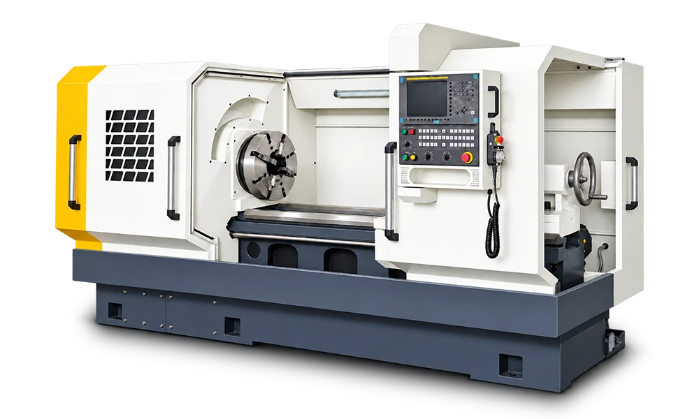
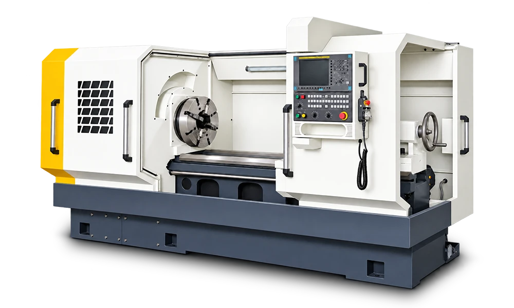
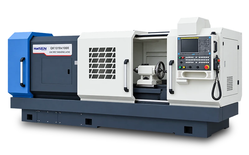
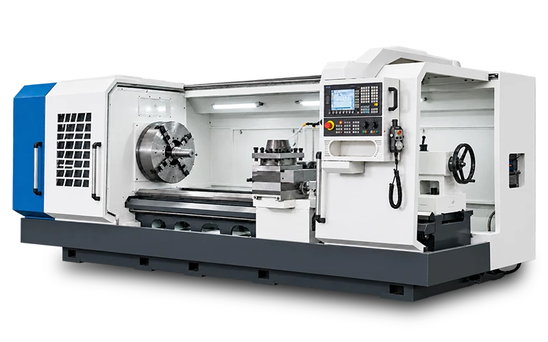
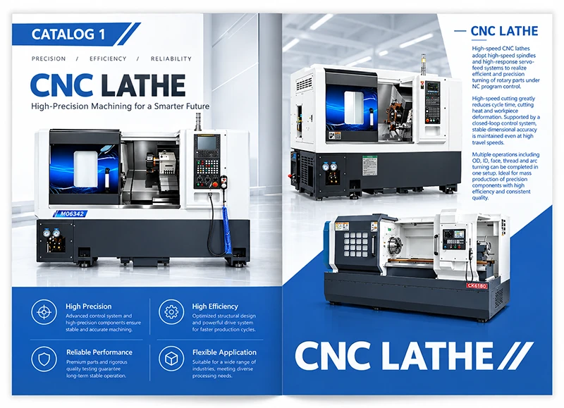
What is a CNC pipe threading lathe used for?
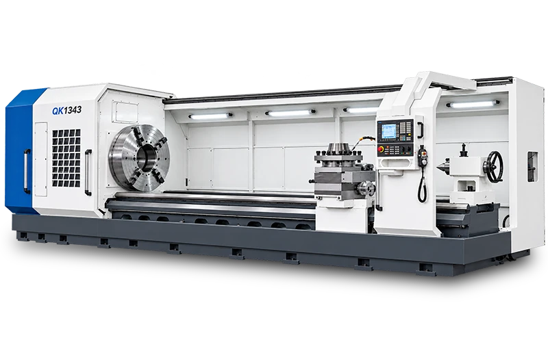
A CNC pipe threading lathe machines threads and related end features on pipes, tubes and other cylindrical workpieces. The spindle rotates the workpiece while the CNC coordinates tool movement. During threading, axial feed is synchronized with spindle rotation to generate the specified lead; coordinated radial and axial movement produces a taper where required.
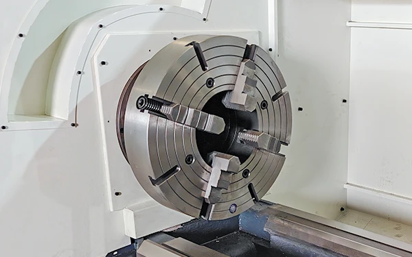
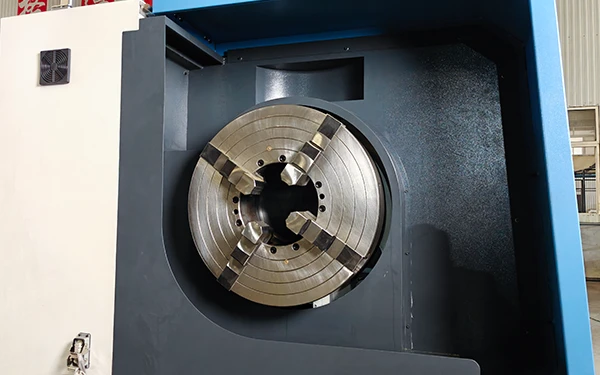
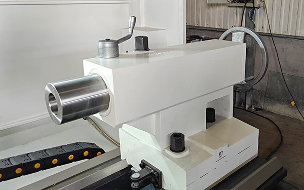
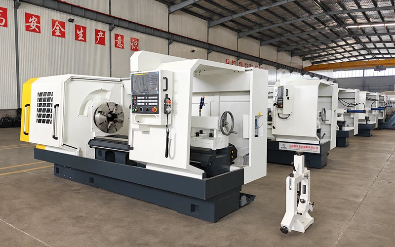
Its large spindle passage and pipe-oriented workholding distinguish it from a small general-purpose lathe. On suitable models, a long pipe passes through the headstock and is gripped by front and rear chucks for end machining. Facing, chamfering, boring and cylindrical turning can also be included where tooling and machine capacity allow. The clamping arrangement and external supports must suit the actual workpiece.
How does a pipe threading lathe differ from a general-purpose CNC lathe?
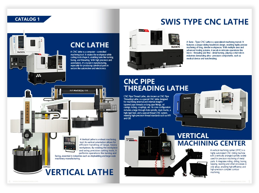
Both machines can turn diameters and cut threads. A pipe threading lathe is designed around pipe handling: a large through-spindle opening, a front-and-rear chuck arrangement on suitable models, and a headstock matched to the required diameter, cutting load and speed range. A general-purpose CNC lathe may also machine pipe ends, but its spindle passage, workholding or clearance can limit the stock it accepts.
Start the comparison with the actual part. Check whether the pipe must pass through the spindle, how much projects beyond the chucks, and which faces and threads need tool access. For shorter fittings or conventional turning work, tooling, machining length and clearance over the bed and cross slide can matter as much as spindle bore.
Is spindle bore the same as maximum pipe diameter?
No. Spindle bore is the diameter of the passage through the spindle; usable pipe capacity also depends on the workholding. For through-spindle machining, the pipe's actual outside diameter must pass through the relevant openings and fit the chuck jaws. Bore size alone does not account for chuck clearance, jaw range, pipe ovality, surface condition or the clearance needed for loading.
Also distinguish actual outside diameter from nominal pipe size, which is a size designation rather than a direct outside-diameter measurement. Check the machine's specified pipe clamping or threading range separately from its spindle bore and swing over bed. Send the maximum actual outside diameter, wall thickness and end geometry for confirmation, especially if the pipe is close to the machine's rated capacity.
Why are two chucks used, and when is external pipe support needed?
Front and rear chucks grip a pipe at two positions along the headstock, helping locate and hold stock that passes through the spindle. Correctly aligned jaws and suitable clamping force help maintain stable rotation during end machining. Thin-walled pipe needs particular attention because excessive jaw pressure can distort it and affect the finished thread.
Two chucks do not support the entire length of a projecting pipe. Long or heavy sections may still require correctly positioned external supports or a suitable steady rest. Unsupported rotating stock can bend and whip, so support position, alignment, permitted speed and guarding must be assessed together. Specify the complete pipe length, mass and projection on each side when confirming the workholding arrangement.
Can the machine cut internal, external and tapered pipe threads?
Internal, external, parallel and tapered threads can be machined when the selected CNC functions, tooling and working clearances suit the drawing. External threads use an outside threading tool; internal threads require a suitable boring bar and sufficient bore access. Internal reach, tool overhang and chip evacuation can limit a job even when the pipe fits the chucks.
Specify the exact thread designation, pitch or lead, taper, handedness and tolerance. NPT, BSPT and other connection types use different geometries and require matching tooling and programming. Thread acceptance also depends on the applicable dimensions and gauging or inspection procedure. A programmed threading cycle alone does not establish conformity with a named connection standard; confirm the complete machining and inspection requirements before selecting the configuration.
Does machine length determine the length of pipe that can be threaded?
Not by itself. For through-spindle end threading, the whole pipe does not need to fit between the headstock and tailstock. The pipe can pass through the spindle, with the end to be machined projecting into the working area. In this arrangement, usable pipe length depends on the loading space, workholding and external support system as well as the lathe.
A job that requires turning a substantial length along the bed must also fit the available tool travel and working clearances. Long projections require a support and speed arrangement appropriate to the pipe; a larger spindle bore does not make pipe length unlimited. State both the total stock length and the length to be machined, together with any requirement to process both ends.
Which specifications matter most when selecting a pipe threading lathe?
Begin with the pipe's actual outside diameter, wall thickness, total length and mass. Match these to the spindle passage, chuck opening and jaw range, then check the support arrangement. For work that extends along the bed, compare machining length, tool travel and swing over the cross slide rather than relying only on swing over bed.
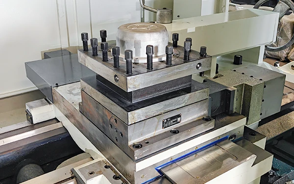
Next review the material, thread form, pitch, taper and required finish against the spindle speed range, available cutting torque and tooling. Motor power alone does not describe the torque available at the intended cutting speed. Finally, confirm tool-post capacity, CNC threading functions, coolant and chip handling, electrical supply and the equipment included in the quotation. These details should be checked for the selected machine configuration.
What information is needed for a CNC pipe threading lathe quotation?
Provide a dimensioned drawing showing the pipe or fitting, actual outside and inside diameters or wall thickness, total length, and the features to be machined. Include the material grade and condition, thread designation and applicable specification, tolerances, surface finish and inspection requirements. Clarify whether the job involves new threads, re-threading, one end or both ends.
Add the expected production quantity or output target, preferred CNC control, available electrical supply and destination country. State whether you need manual or powered chucks, external pipe supports, a particular tool post, chip handling or loading equipment. If a model has not been selected, the drawing and stock information provide a basis for reviewing machine capacity and defining the supply scope before a quotation is prepared.