This article will explain Straight Turning in detail, helping you understand its role in lathe machining and the key factors that influence the process.
What Is Straight Turning?
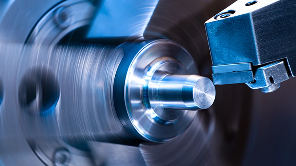
Straight Turning is one of the most fundamental operations in lathe machining. Its primary function is to reduce the outer diameter of a cylindrical workpiece to a specific and uniform dimension.
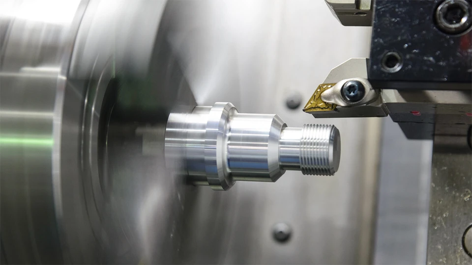
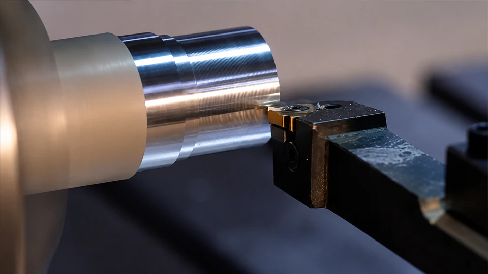
The word “straight” in this context does not mean the machining process is simple or lacks technical depth. Rather, it describes the physical motion of the cutting tool and the resulting surface feature. During the operation, a single-point cutting tool feeds in a straight line parallel to the rotational axis of the workpiece. This continuous linear movement removes material evenly from the outer surface, producing a true, straight cylinder.
Why Straight Turning Matters in Lathe Machining
Straight Turning is rarely the final or only operation performed on a workpiece, but it is often one of the most foundational. It establishes the baseline geometry and primary dimensions of the cylindrical component.
The accuracy achieved during Straight Turning strongly influences the success of subsequent machining stages. If this initial process produces poor surface quality or inaccurate diameters, downstream operations such as threading, grooving, or knurling may inherit and further expose these errors. The straight-turned surface often serves as an important reference for the rest of the manufacturing cycle.
Although the linear motion appears simple, consistent and high-quality results are not guaranteed by default. The actual outcome depends on several variables, including the mechanical condition of the lathe, the condition of the cutting tool, material properties, and the selected machining parameters.
Basic Working Principle of Straight Turning
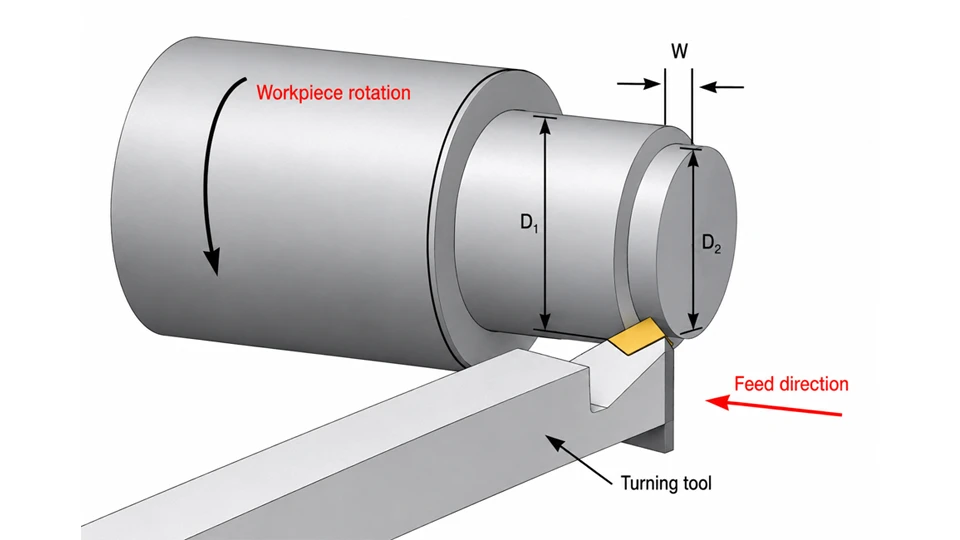
The mechanics of straight turning rely on the continuous interaction between two fundamental motions: the primary rotation of the workpiece and the linear feed of the cutting tool.
First, the raw cylindrical workpiece is securely held and driven by the lathe’s spindle. This continuous rotation provides the main cutting motion, generating the surface speed and mechanical force required to shear the metal.
Simultaneously, a single-point cutting tool engages the outer diameter of the spinning material. The tool moves smoothly and continuously parallel to the workpiece’s longitudinal axis. This linear travel constitutes the feed motion.
As these two motions intersect, the cutting edge systematically shears away a continuous layer of material from the exterior. By maintaining a precise, fixed distance between the tool tip and the rotational center of the spindle, the operation progressively removes the excess material. This fundamental shearing mechanism is what ultimately shapes the rough stock into a uniform, highly concentric cylindrical surface at the targeted diameter.
Tooling and Workholding in Straight Turning
Reliable Straight Turning requires a rigid mechanical setup to resist cutting forces and maintain dimensional control. This physical stability is strongly influenced by how the workpiece is secured and by the characteristics of the cutting tool.
Workholding Methods
Most cylindrical stock is gripped by a three-jaw self-centering chuck for fast and convenient setup. For higher precision requirements or workpieces with irregular geometry, a four-jaw independent chuck or collet may be used.
A critical workholding challenge in Straight Turning is managing workpiece length. When long or slender shafts are machined, radial cutting forces can push the material away from the tool and cause deflection. Where additional support is required, the free end can be supported by a tailstock center. For exceptionally long workpieces, a steady rest may be added to provide mid-span support and reduce bending.
Tooling Characteristics
Straight Turning typically employs external turning tool holders fitted with indexable inserts, commonly made from carbide. Although insert selection varies with the workpiece material and machining conditions, the physical geometry of the tool has a direct effect on cutting stability.
The insert nose radius is a key factor. A larger nose radius provides a stronger cutting edge and can support heavier cuts or produce a smoother surface under stable conditions, but it also increases radial cutting force. A smaller nose radius reduces cutting resistance and may help limit vibration when machining slender or less rigid parts.
Basic tool angles, including rake and clearance angles, influence how efficiently the cutting edge shears the material and clears chips from the cutting zone. Correct geometry also helps prevent the tool from rubbing against the newly machined surface.
Key Cutting Parameters in Straight Turning
Straight Turning depends on a balanced combination of cutting speed, spindle speed, feed rate, and depth of cut. These parameters control how quickly material is removed, how much load is placed on the tool, and what type of surface is produced.
Cutting Speed and Spindle Speed
Cutting speed is the relative speed between the cutting edge and the workpiece surface. Spindle speed is the rotational speed of the workpiece, measured in revolutions per minute.
The required spindle speed changes with workpiece diameter. A smaller diameter generally needs a higher spindle speed to maintain the same cutting speed, while a larger diameter requires a lower spindle speed. Tool material, workpiece material, and machining conditions must also be considered.
Feed Rate
Feed rate is the distance the tool travels along the workpiece axis during each revolution. It directly affects productivity and the spacing of tool marks on the machined surface.
A higher feed rate removes material faster but usually produces a rougher surface and increases cutting load. A lower feed rate can improve surface finish, although an excessively low feed may cause rubbing instead of efficient cutting.
Depth of Cut
Depth of cut is the radial thickness of material removed in one pass. Because the tool removes material from the radius, a 1 mm radial depth of cut reduces the workpiece diameter by approximately 2 mm.
Larger depths of cut are normally used during rough turning to remove excess stock efficiently. Smaller depths are used during finish turning when dimensional control and surface quality become the main priorities.
Coolant and Cutting Conditions
Coolant can reduce heat, support chip evacuation, and improve tool life during Straight Turning. However, its use depends on the workpiece material, insert grade, cutting speed, and machine setup. Some machining conditions are designed for dry cutting, while others benefit from a stable coolant supply.
No parameter should be selected in isolation. Increasing speed, feed, or depth of cut changes the cutting force, heat generation, tool load, and machine power requirement. Stable Straight Turning therefore depends on selecting parameters that suit the material, tool, workpiece rigidity, and required machining result.

Straight Turning Process Flow
Straight Turning follows a clear sequence from drawing review to final inspection. Each stage establishes the conditions required for the next, so errors introduced early in the process can affect the final diameter and surface quality.
1. Review the Machining Requirements
The process begins with the part drawing. The required diameter, turning length, dimensional tolerance, surface finish, and any remaining machining allowance must be identified before setup.
2. Prepare and Secure the Workpiece
The workpiece is cut to a suitable length and clamped in the selected workholding device. Its position, runout, and unsupported length are checked to ensure that it can rotate safely and remain stable during cutting.
3. Set the Tool Position
The external turning tool is mounted securely and aligned with the workpiece centerline. The tool offset or reference position is then established so the machine can control the final diameter accurately.
4. Perform the Roughing Pass
Rough turning removes most of the excess material and leaves a controlled amount of stock for finishing. The objective is efficient material removal rather than achieving the final surface condition in one pass.
5. Complete the Finishing Pass
The finishing pass brings the workpiece to its required diameter and surface finish. It normally removes a smaller amount of material under more controlled cutting conditions.
6. Inspect the Machined Surface
After turning, the diameter is measured at several positions along the machined length. Surface finish, straightness, and cylindrical consistency are also checked against the drawing requirements. Any necessary tool-offset correction is made before the next part or final pass.
Common Quality Problems in Straight Turning
Even with careful preparation, straight turning can produce defects if the machining dynamics are unbalanced. Identifying the physical manifestation of these issues is the first step toward correcting them.
- Taper on the Turned Surface:
- Manifestation: The workpiece fails to maintain a uniform diameter, gradually becoming thicker or thinner along its longitudinal axis rather than forming a true cylinder.
- Cause: This is primarily caused by workpiece deflection under radial cutting pressure (especially on long, unsupported shafts) or a physical misalignment between the lathe’s spindle axis and the tailstock center.
- Chatter Marks (Vibration):
- Manifestation: The machined surface displays distinct, repetitive wave-like patterns, often accompanied by a high-pitched squealing or groaning noise during the cut.
- Cause: Chatter is a resonance issue. It occurs when mechanical rigidity is compromised, frequently stemming from excessive tool overhang, unstable workholding, or pushing a depth of cut that exceeds the machine’s structural stiffness.
- Poor Surface Finish:
- Manifestation: The final texture appears torn, hazy, or physically fails to meet the specified surface roughness (Ra) requirement on the drawing.
- Cause: This defect typically results from feeding the tool too quickly relative to the insert’s nose radius, using a worn cutting edge, or material welding itself to the tool tip (Built-Up Edge) due to incorrectly matched cutting speeds.
- Chip Control Problems:
- Manifestation: The cutting process generates long, continuous, stringy chips that aggressively entangle around the chuck, the tool post, or the workpiece itself.
- Cause: This happens when the feed rate and depth of cut are not aggressive enough to force the material into the insert’s built-in chipbreaker, failing to curl and snap the metal into manageable pieces.
- Heat-Related Dimensional Inaccuracy:
- Manifestation: The part diameter measures perfectly within tolerance while clamped in the machine but falls out of tolerance after sitting on the inspection bench.
- Cause: Excessive cutting friction generates severe heat, causing the metal to temporarily expand during the finishing pass. Once the part cools to room temperature, thermal contraction alters the final machined diameter.
How to Improve Straight Turning Results
Achieving exceptional accuracy and surface quality in straight turning requires moving beyond basic setups to actively controlling machining dynamics. The focus must be on maximizing system rigidity and optimizing the cutting environment.
- Maximize System Rigidity: Eliminate vibration by keeping the cutting tool overhang as short as physically possible. For the workpiece, always deploy a tailstock or steady rest when the length-to-diameter ratio exceeds 3:1 to effectively counteract radial deflection.
- Strategic Tooling Selection: Match the insert’s nose radius directly to your required surface finish and feed rate. Additionally, utilize the correct built-in chipbreaker geometry to ensure chips curl and snap into manageable pieces rather than wrapping around the tool post.
- Separate Roughing and Finishing: Never compromise parameters by trying to achieve bulk material removal and a pristine finish in a single pass. Use aggressive depths of cut to remove material efficiently during roughing, then switch to a dedicated finishing tool with higher surface speeds and fine feed rates for the final pass.
- Thermal and Chip Management: Flood the cutting zone with properly directed coolant. This stabilizes the thermal expansion of the workpiece to ensure dimensional accuracy, lubricates the tool to prevent built-up edge (BUE), and forcefully flushes chips away before they can scratch the newly turned surface.
- Verify Machine Accuracy: The ultimate capability of the straight turning process is capped by the mechanical condition of the lathe itself. Regularly verify spindle alignment and ensure axis guideways maintain tight clearances to prevent backlash-induced dimensional errors during the linear feed.
Conclusion
Straight Turning may appear simple, but reliable results depend on far more than a straight tool path. Workholding, tool condition, machine rigidity, cutting parameters, heat control, and inspection all influence the final diameter and surface quality. When these factors are properly managed, Straight Turning becomes a stable and repeatable process for producing accurate cylindrical surfaces.
For manufacturers evaluating CNC turning capability, machine stability and long-term process consistency are equally important. Haisen supplies CNC lathes and related metalworking equipment designed for practical production needs, with support for machine configuration, customization, and after-sales service across different machining applications.